I’ve been doing a bit more gardening recently – last year I had some success with Busy Lizzie (Impatiens)) and Geranium (Pelargonium) cuttings. Also with Cape Primrose (Streptocarpus) and African violets (Saintpaulia), which are excellent indoor plants with a very long flowering period. Indeed, I’ve got Impatiens and Pelargoniums in flower right now – in the middle of January, although the flower buds were formed last year.
I’m not that happy with the African plants as they’re clearly unhappy with the very dark weather we’ve had since December, so I’ve invested in some ‘full spectrum’ grow lights. These use LED chips mounted on a circular board in a GU10 housing, which is convenient as I have some desk lamps that I used for illuminating an art installation, but which are now languishing in a cupboard.
They give out a very bright magenta glow of the sort that I see has been mistaken for the Aurora borealis when used in countryside glasshouses.
I see that it is suggested that you have them on for 16 to 18 hours a day. Currently, sunrise is about 7 am and sunset about 4.30 pm. Since there is even some sunshine possible in the mornings, I’ll probably run them from 4 to 10 pm initially, just to see what happens.
I’m working on a project that is powered by a battery (3 AA cells).
The circuit has a low quiescent current, but the battery won’t last long if it is left permanently on. So I want an indicator to warn when it is switched on. An LED is fine, but it would more than double the current consumption if running a a suitable brightness, thus defeating its own object. The answer may be to flash it occasionally as this might even help to draw attention to it.
There are many possible ways of doing this, but I need one that has very low current consumption, and the current consumption of the various options is not always clear.
A 555 timer chip is a possibility, but it has quite a high current consumption, unless you get a CMOS version.
A transistor multivibrator has too many components – I want it to fit into a tiny box – and again has a significant current consumption.
There is a special chip that has a built-in timing circuit specially for driving a flashing LED, but the flashing rate is fixed and I can’t find details of its current consumption.
There are flashing LEDs, but again they seem to have quite a high current consumption
An optocoupler-driven R-C timing chip. They are cheap and use few components that can be selected for a suitable duty cycle.
I’m going to choose option 5. The circuit diagram is below:
I’ve seen some explanations of this circuit which I think are incorrect. I think it works as follows.
Opto-Flash Circuit
When first energised, Pin 1 (the anode of the internal LED) is at ground potential, so the internal LED is off along with the output circuit via pins 3 and 4. C1 starts charging via R1 until the potential at Pin1 reaches the conducting voltage of the internal LED, about 1.4 volts. The time constant is (R1+R2)*C1. When the internal LED starts to conduct, the output also starts to conduct and the external LED illuminates, raising the potential of pins 4 and 3 to the supply voltage less the forward voltage of the LED (around 2 v), i.e. pin 3 rises to 2.5v.
Since the potential across the capacitor does not change immediately, this raises its positive plate to about 3.9 v, driving the internal LED hard, and causing the external LED to light brightly – its current is limited by the 1k resistor R2. The capacitor discharges rapidly through the internal LED until it reaches the turn-off voltage of the internal LED, allowing the external LED to illuminate briefly until the capacitor has discharged. At this point, the voltage on the negative plate is pulled back down to zero by R2.
The capacitor is now in its initial state and the process repeats.
The quiescent current is determined by V/(R1+R2), i.e. 4.5/7000 = 640 µA, though each short pulse will be (4.5-2)/1000 = 2.5 mA. The duty cycle will be slightly shorter than the time constant of 1.5 s shown by the above calculation, because the circuit conducts before C1 becomes fully charged.
The PIC817 opto-isolator costs around 40 pence and the circuit only needs three components. They can be wired compactly without needing a circuit board as shown below:
Opto-Flash wiring
I’m wondering about ways of reducing the current consumption further and if successful I will add to this blog.
My house has a period brick fireplace that had a ‘living flame’ gas fire in it, but I had the chimney taken down when having an extension built. But a dark fireplace is uninviting, so I bought a ‘Silk Flamelight’ which looks fine, and it has a ‘tape’ of red LEDs in the base to give the effect of glowing embers. I like it, but it would be nice if the glow of the embers could wax and wane as in a real fire.
I did try out some ‘flame effect’ LEDS, but I don’t like them because the flame is clearly periodic and ultimately quite annoying. It seems that these are powered via what are essentially counter chips with feedback connected to give some pseudo-randomness.
But I came across some red ‘candle flame effect’ LEDS. These have some sort of microscopic randomiser chip within them. They do flicker nicely, but they are not bright enough.
Figure 1 Booster Circuit Wiring
It occurred to me that I could use the varying voltage on the anode of the LED to drive a simple transistor amplifier, as shown in the diagram. The resistor R1 in series with the anode of the flicker LED will cause the voltage on the anode to vary according to the current that it is drawing. If we assume this is to be 10 mA when fully on, the voltage drop across a 200 Ohm resistor is is nominally 2 v, giving an anode voltage of 3 v, which is the nominal forward voltage of the flicker LED. When it is fully off, the voltage will rise to the supply voltage of 5 v.
This range of 3 v to 5 v needs to turn the transistor TR1 off and on. By placing the bright LEDS on the emitter of TR1, and assuming they have a forward voltage of 2 v, then TR1 will conduct whenever the voltage on its base exceeds about 2.6 v, because a transistor has a 0.6 base-emitter voltage drop.
This means that the bright LEDs will always be on a little, and will be at their brightest when the flicker LED is off.
Effect of changing resistor values
Resistor R1 affects the range of voltage at the base of TR1 – experimentation show that a value of 100 ohm meant that TR1 was always fully on, and a value of 350 ohm increased the amount of flicker from fully on to fully off. However, since embers are always glowing to some degree, a value of 200 ohm was thought to be optimum.
The value of R3 affects the current draw of the bright LEDs, so needs to be chosen taking into account their forward voltage. Assuming this is 2 v, then a 100 ohm resistor gives 15 mA per diode in the arrangement shown, or 30 mA if only one diode.
LED ‘Tapes’
To simulate the glow of embers in a grate, I need a row of LEDs, and it occurred to me that an RGB strip of LEDs would allow me to control their colour which would be nice. A search showed that LED ‘tapes’ (a long line of surface-mount LEDS fixed to a backing tape) have the resistors in series with each group of diodes. The LED tapes are designed to use a common positive rail, usually 12 or 24 volt, so they need to be in the collector circuit of the output transistor. A separate circuit is needed for each colour. This will require some reworking to accommodate these factors.
Figure 2 Using blocking capacitor
The problem is to get the right biasing of the output transistor. As we have noted, the voltage at the junction of R1 and the Flicker Diode varies between say 3 v when fully on up to the supply voltage (now 12 v) when fully off (it’s not possible to measure accurately with my digital multimeter as this only samples about twice a second.) One solution is to use a DC blocking capacitor in the transistor base circuit, as in Figure 2. The 20 k resistor allows the voltage on the base to build slowly (the time constant is 20 k x 10 µ = 0.2 sec), so the voltage on the base will follow that on the flicker diode but without the DC bias.
Flickering Embers
This actually worked very well in terms of conveying a strong flicker to the output, but I want to put the tape of LEDS into the bottom of the hearth to look like flickering embers, and these don’t switch quickly on and off, but gently vary with the air flow through the grate.
The glow of embers varies between bright red and bright yellow. Yellow is produced by mixing red and green, and after some testing I decided that the red needed to be at full intensity all the time, and only the green needed to flicker. More than that, with green at full intensity, this drowned out the red, and we had green embers – not at all natural!
Flicker Circuit 3 Using biasing resistors
So, ultimately, I ended up with circuit 3 . This uses a fairly high value of 6.4k for R1 in the anode of the flicker diode: it still flickers as required, but is fairly dimly lit. This doesn’t matter since it is only being used to generate a flickering voltage to the transistor. R2 and R3 act as a potential divider and apply a voltage varying between 1.2 and 4.8 volts on the base of the transistor, so it is always conducting. This is fine – it means the embers are always slightly orange. In fact, they were slightly too orange, and it was necessary to put a 100 Ω resistor in series with the output to the green LED channel.
This works fine – if I have any disappointment, it is that I don’t seem to be able to get a really bright yellow: increasing the green channel seems to go rather suddenly from orange to green, but maybe I didn’t experiment enough. For information, the values of the resistors are not critical. Reducing the value of R3 increases the amount of flicker but reduces the overall brightness, because the transistor has a lower amount of base bias. Increasing the value of R2 reduces the brightness because it also reduces the amount of base bias.
Elegance
Although this works acceptably well for my fireplace glow, and is extremely economical on components, I’m not sure how engaging it would be for garden ‘party’ lights.
It seems to me that we could use the output of the flicker diode to modulate the output of a pulse width generator. It appears that this can be done with a 555 ‘timer’ chip, but this is a whole new ball game for me. This chip, which is very inexpensive, is essentially a multivibrator which can be controlled by external resistors and capacitors to produce monostable and astable (usually square wave) output. The 555 is very cheap and has enough switching capacity for a short LED strip. For larger strips you would need to buffer the output through a power MOSFET.
I’m thinking I will try this out and let you know if it works.
We have bought two nice bedside wall reading lamps and would like to be able to switch either of them on without having to reach across the bed. Moreover, the wiring has to be within a stud wall, so it needs to be simple to install.
Before going any further, I should make it clear that my suggestions below are intended to be followed by those who know about electricity and wiring, and who understand the safety rules. Don’t fiddle with mains electricity unless you have the required knowledge.
Approved UK wiring for 2-way lights
Figure 1 – Standard 2-way wiring
The approved wiring standard for two-way lamps is shown in Figure 1. 3-core and earth cable is used to connect the switches as shown. The brown wire is the live that runs between the switches and connects the switch contact usually marked L1. The grey wire is the ‘Switched Live’ and runs between the switch contacts marked L2. The black wire is the ‘common wire’ that runs to the central contact of both switches. Thus the wiring is simple and like-for-like in both switches.
The lamps are connected to the Switched live wire, coloured Grey, usually L2 in the switches. There can be several lamps connected to the switched live wire. A neutral must also be supplied, usually to the ceiling rose. The lamps will be off when both switches are in the same direction and on when the switches are in opposite directions. It is not possible to have one lamp on and the other lamp off. But we want to be able to have this with our reading lamps.
Controlling a separate lamp
Figure 2 – Adding an independent lamp
If you connected a lamp between the common (black) and neutral, Figure 2, then it would be on whenever the common (black) is live. In this circuit, the common is live when either switch is ‘down’. However, B1 cannot come on unless the common is live, so you can have B2 on and B1 off, but not the other way round. Again, this is not what we want for our reading lamps. We want to be able to have either one on or off.
There is a further issue. The lamps are to be mounted onto a stud wall. The other side of the wall is a cupboard, but I want to minimise the wiring, so I have decided to mount small switches directly into the lamp back boxes, which means that each box needs a neutral as well as a switched live. Obviously the standard 3-core wiring doesn’t accommodate a neutral, so I’d need to run an extra wire.
Independent control of a second lamp
Figure 3 – Separate control of 2 lamps
Now, there is an acceptable (but not recommended) alternative to the standard 2-way wiring as shown in Figure 3. (There are also some other arrangements which have been used in the past but are considered unsafe, so they’re not described here.)
In essence, the wiring in Figure 3 feeds the Live into just one switch (SW2 in Fig 3), and the lamp (or several lamps) are connected to the switched live taken from the other switch (B1 connected to SW1 in Fig 3). Either switch will turn all these lamps on or off. Furthermore it is possible to just use a two-core cable between the switches. But that is one reason this isn’t liked: the live could be fed from one circuit and the neutral from another circuit, which can mean that the lamps might not be isolated by a single circuit in the fuse-board: this is not only risky, but can also lead to problems with some residual current circuit breakers.
In our case, we will use a 3-core and earth cable, and we will feed the power in at one switch box and lead the neutral to the other switch box via the black core of the cable.
Separate (independent) control
We can connect a second lamp or lamps between one of the switched lives and the neutral. As well as providing the neutral, this arrangement has another advantage – both lamps can be switched on or off separately, if we connect them as shown.
With both switches SW1 and SW2 up as shown, both lamps are on.
If SW1 is now moved down, and SW2 is up, B1 will go off and B2 will remain on. So SW1 can switch its light B1 off without affecting the other light B2.
SW1 is left up, but SW2 is moved down, both lamps will go off. This is as expected.
If SW1 is now moved down whilst SW2 is left down as well, B2 will stay off, but B1 will come on. This means that SW1 can switch on its own light.
In short,
B1 & B2 are on when SW1 and SW2 are up B1 & B2 are off when SW1 is up and SW2 is down.
B2 will be on whenever SW2 is up.
B1 will be on whenever both SW1 and SW2 are in the same direction.
To get B1 on and B2 off, SW1 and SW2 should be down.
To get B1 off as well as B2, turn SW1 up
To get B2 on and B1 off, turn SW2 up and SW1 down
I will be installing this and will let you know how I get on.
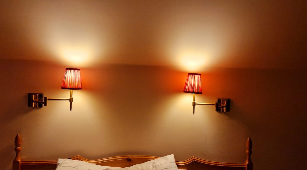
We decided that some better reading lamps would make our bedtime reading more comfortable and after some internet searching we bought a couple of brass wall lights on adjustable elbows from Pooky Lighting. They are a pleasing retro design with pretty patterned shades. However, they don’t have a switch built in and came with no fitting instructions. Plenty of opportunity to play!
Lamp mounting
Mounting
The mounting is basically a rectangular brass box with a steel U-bracket drilled with two holes. They supply a couple of steel screws and plastic wall plugs, which didn’t seem at all ideal for fitting directly into the plasterboard stud wall, as there is quite a lot of shear force when the lamp arms are extended.
Mounting bracket
The electrical connector supplied is simply a 3-way ‘chocolate block’ flying connector fitted to the end of the lead going to the lamp bulb. I would need to have some sort of back box, as I didn’t want the connection to be floating around loose inside the wall cavity, and there wasn’t really enough room to house these inside the shallow mounting box of the fitting.
The mounting box and flying lead
Fitting a switch
Moreover, where to fit the switch? I didn’t want to make yet another hole in the studwork to accommodate a wall switch. One problem with studwork is that you are never quite sure where the studs and noggings might be. I have got a wall tester, but it isn’t completely reliable.
My father always tested for studs, etc, by plunging his electrical screwdriver into the wall. Whilst this is certainly a good idea before getting out the pad saw, it does rely on inspired guesswork if you want to avoid a lot of making good afterwards.
2-way switch
I decided that I would mount the switch into the underside of the brass back-box, where it could be reached whilst lying down. I had wanted a string-pull switch but couldn’t find any from the usual suppliers, so I decided on a small toggle switch. The one I bought has a central ‘off’ position, which I wasn’t sure I needed, but should be OK. It’s rated at 2 A at 250V, which is 500 watts. Since LEDs will only be about 4 or 6 watts, this is plenty. The only downside is that the connections need to be soldered. I used wire colours to match the connections, i.e. red, brown and grey. Needless to say, this left little space for any other connections inside the back-box.
Fitting a standard back-box
The fitting bolted to a suitably-drilled blanking plate
I had a sudden inspiration – you can get standard-size back-boxes for stud walls, that have a clever clip to hold them in place. And it turned out that the back-box of the light-fitting was the same height and about half the width of a standard back box. So I bought a couple of brass blanking plates, drilled them with suitable holes and bolted the steel mounting bracket to the brass blanking plate. The ‘chocolate-block’ connector can then be lead through the blanking plate and the supply can be neatly connected within the back box. When all connections are complete, it is easy to bolt the light assembly into place.
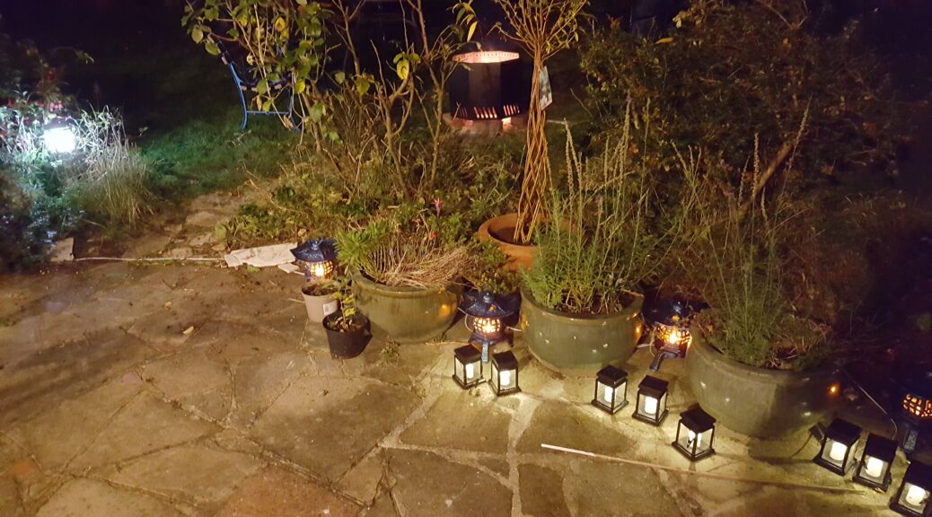
I have just made some flickering flame lights for the garden. Since it is hard to show a flickering flame in still photos, I have made a video of the project and put it on YouTube here.
During the lockdown, at my request my builder installed two outside lights with PIR movement detectors, but they were just white LED floodlights, glaring and looking awful. I found the movement detectors were unreliable – staying on all the time or not coming on at all, or not detecting people approaching.
I really wanted some stained glass porch lanterns, but I couldn’t find any. In fact, finding pleasant lighting at a fair price has been very difficult. After hours searching the internet, I found some ‘Quoizel’ lanterns with Tiffany glass shades that I really liked, advertised by several companies. Following enquiries, I found that like so many on-line firms nowadays, the companies don’t actually have them in stock, but ‘back-order’ them when you place an order. I’ve had bad experiences with this on other orders, but having chosen a firm, I pressed them on deliveries, being aware that things could get difficult with the various lockdowns and the end of the Brexit transition period. I was met with the despairing reply that ‘Nothing is Made in Britain these days’ and that these came from Poland! I decided to chance it, as the firm was well-established, and to be fair they did arrive on the promised date some weeks later. But ‘Made in China’ of course! The Tiffany glass is very pretty, though the lantern is made of pressed mild steel and the so-called ‘Valiant Bronze’ finish is nothing more than brown paint with streaks of red in it! To be honest, I didn’t really expect anything else.
The ‘Quoizel’ lantern
But the mounting system is dreadful. Basically a thin pressed steel perforated strip with two steel captive bolts that protrude through two holes in the painted rectangular back plate. This is very weak when you consider the swaying effect caused by wind loading in stormy conditions. There is also a bottom glass-retaining panel held on by two similarly fiddly nuts (that they quaintly call ‘mounting balls’). It would be so easy to lose these or to drop the glass panel.
Worse, there is no cable inlet cut-out. Since the instructions are specifically to mount it on a wall, do they expect you to channel out the wall? No way! I suppose I could have hacked it with a saw, but that would damage the paint, as would screwing the box to a very rough brick wall.
The back-box showing flying lead for electrical connection
The electrical connection is to a flying lead terminating in a press-fit plastic box. Not waterproof in the slightest. Moisture has a habit of ingress into any enclosed space just through the ‘breathing effect’ of temperature rise and fall. Moreover, there is no system to support the unit while you make the connections. I had to lash it up with some wire.
When you read the small print of the installation instructions, you are told to ‘caulk’ around the mounting box and the wall, and also around the fixing nuts. My guess is that it wouldn’t pass the electrical safety tests otherwise.
Home-made plywood pattress showing the thin metal mounting strip supplied
I decided that the only decent way to mount the lanterns was to custom-make a couple of pattresses from some strips of plywood that were waste from another project, which I had to paint black for weatherproofing. I cut a slot for the cable at the bottom of the pattress. I will ‘caulk’ these to the wall, but it is too cold and stormy right now, as the sealant needs to be applied when the temperature is above 5 degrees. So I have filled the nuts with grease and hope this will hold the fort for now.
PIR detector
As to the PIR movement detector, I bought a LAP8461V which is mounted separately from the lanterns, allowing its position to be optimised without compromising the position of the lanterns. The detector has adjustments for sensitivity to movement, for ambient light level (so it can be set to come on only after dark) and for on-time. It also has a simple manual override so that it stays on (or off).
Schematic Wiring Diagram
To give me flexibility in positioning the sensor, I have connected both lanterns to a weatherproof junction box which carries the supply and earth to all items. They are connected to the neutral and switched live supplies. It would be possible to daisy-chain the supply from one lantern to the next, although the connector in the lantern would need to be changed as it won’t accommodate extra wires. A 3-core and earth lead runs from the junction box to the sensor. The 3-core lead carries neutral, live and returns the switched live supplies, as the sensor requires a power supply in order to operate. I used conventional two-way switch cable for this.
It is working very well and I’m delighted with the appearance. Only time will tell on their durability.
In the old days, buying a light bulb was simple.
• How many Watts?
• Pearl or clear?
There were some special bulbs, such as for projectors and for photography, but these weren’t mainstream and you’d have to go to a specialist supplier to get one.
Bewildering choice
Nowadays, the choice is bewildering, and something I’m having to resolve as I’m refurbishing my house, so I thought it would be useful to summarise some of the considerations.
Incandescent bulbs were progressively phased out in the UK from 2009 to 2014, being initially replaced by ‘compact fluorescent’ or CFL bulbs and subsequently by LED bulbs.
‘Halogen’ incandescent lamps are still permitted but are generally only used where a small light source is needed, such as in projectors, car headlamps and for some decorative uses. These are most efficient when operated at a low voltage (generally 12 volts) so these need a transformer in domestic use.
LEDs are the norm
It is fair to say that LEDs are now the norm. They are bright, come on immediately, generate little heat and have a long life. They are not perfect. The main disadvantage is that they can give poor colour rendering. So lets look at this.
Black body radiation
The CIE colour space and black-body colour temperatures
An incandescent bulb radiates light due to the high temperature of the filament. The radiation [nothing to do with radioactivity] is close to a ‘black body’ radiation, which is dependent on the temperature of the heated object – in this case the filament. We are used to seeing things under such illumination, as this is approximately what we see under sunlight (ignoring the effect of atmospheric absorption). A black body emits light in a continuous spectrum which peaks at a certain frequency (colour) according to its temperature. The higher the temperature, the bluer the peak of its spectrum. The ‘Colour temperature’ of a lamp means the temperature of a ‘black body’ when heated sufficiently to glow at the same colour that the lamp gives out. It is usually expressed in ‘degrees Kelvin’ which are 273 degrees more than degrees Celsius – in other words, water freezes at 273 degrees Kelvin. 0 degrees Kelvin is ‘absolute zero’, where an object has no thermal energy.
Colour Temperature
On the colour temperature scale, a bright red glow is 1000 degrees Kelvin. At 2000 degrees Kelvin, there is a bight orange glow, rising to a bright yellow glow at 3000 degrees, a yellow-white glow at 4000, an almost white glow at 5000 and a pure white glow at 6000. At 7000, glow is a blue-white and at 8000 it is distinctly blue. By 10000, we are looking at a bright sky-blue colour. The colour temperature of a typical incandescent or halogen bulb is about 3200 Kelvin.
How LEDs work
However, LEDs don’t work by heating an object. They work by ‘exciting’ electrons to vibrate within atoms, which when they fall back to their rest state emit a photon, depending on the material they are made from. Nowadays, most LEDs emit photons in the blue or near ultraviolet range, but the blue/UV light is absorbed by a phosphor coating that emits visible light in the yellow range of frequencies (which is why the surface of the LED looks yellow when not illuminated). By adjusting the balance between the blue of the LED and the yellow of the phosphor, the light can look white (often ‘warm white’, or ‘cool white’ but in reality it omits large parts of the spectrum, especially in the red. This can mean that the colour rendering of LEDs can be very poor, particularly for skin and other surfaces containing a lot of red. For this reason, lamps are now given a ‘colour rendering index’ (CRI) which indicates how closely the lamp reveals the colours of an object compared with a natural light source. A CRI of 100 means that the lamp shows colours exactly as they appear under ‘standard’ daylight. The test is done by looking at special test colour samples under the lamp and under light of the reference ‘colour temperature’ and rating the differences observed.
Colour rendering
Spectrum of different lights
Typical ‘white’ LEDs have a CRI around 83, which is better than old fluorescent tubes, but far from ideal, so this information is often omitted in marketing details. However a CRI above 90 is needed for good colour reproduction. It is possible to get better colour rendering by using phosphors that emit red, green and blue light.
A warm white LED has a colour temperature of 2700 K, which is considerably more yellow than an incandescent bulb.
A particular difficulty can exist for film and video lighting, because the spectrum of the LED, even with a high CRI, may not match that expected by the colour sensors in the camera. For this reason, a special colour rendering index has been developed for video use.
Luminous efficiency
In the old days, you knew how bright a 100 w or a 60 w bulb would be. LEDs need far less power but the amount of light they give out (which is measured in lumens) depends on their design.
The two-colour white LEDs have the best efficiency, around 120 lm/W whilst 3-colour LEDS produce around 70 lm/W, although the amount of power they need also depends on the efficiency of their control circuitry.
By comparison, an incandescent lamp produces about 15 lm/W and a CFL produces 63 lm/W.
This means that to a rough approximation
Incandescent LED Lumens
100 W 24 W 1800
75W 15 W 1000
60W 11 W 900
40 W 6 W 400
20 W 3 W 300
Dimmable?
The circuitry inside an LED lamp
There is yet another consideration – can they be dimmed? This is not primarily anything to do with the light-emitting diode, but the electronic circuitry within the lamp. All domestic LEDs have control electronics in the base of the lamp, because the LED must be fed with direct current at 2 to 3 volts. There are a variety of ways of reducing the mains voltage of 240 volts to this low value, but usually by ‘chopping’ the incoming AC mains so that it is only on for part of the cycle. The chopped mains ‘fills’ a capacitor until it reaches a certain a low voltage, and then stops the current, which then discharges into the LED. Depending on how this is done, the lamp may not work with a dimmer, which also chops the mains voltage to drive less power into the lamp. Some lamps can be dimmed, but only with a ‘trailing edge’ dimmer.
The lamp cap/base
There is yet another consideration – the lamp base. Traditionally, only the ‘bayonet’ cap was used in the UK, but with the influence of Europe, ‘Edison Screw’ fittings have become very common. Both these ‘caps’ are available in different sizes. It is not part of this article to consider the pros and cons of the two types of fitting. Most of the lamps described above are available in these two ‘caps’.
Bi-pin caps
There are also many types of ‘bi-pin’ fittings which originated for different purposes. G4 is a small bi-pin fitting originally designed for low-voltage halogen lamps. G9 is a slightly larger fitting used with higher-power bi-pin mains voltage lamps, and G10 is a large bi-pin fitting intended for high-power mains halogen lamps. However, these have all be re-purposed so care must be taken that your lamp is for the correct voltage as well as the correct cap.
Considerations when choosing
So, when choosing and LED bulb, the main considerations are:
the cap/base to fit the lampholder
the voltage of the bulb 230/240 volts in the UK, but may be 12 v in fittings with a transformer to replace some halogen bulbs
The colour temperature
2700 = warm white, (i.e. yellow)
4000 = natural white (i.e. sunlight)
6000 = cool white (i.e. skylight)
Dimmable or not
Colour rendering (if you are doing art/design work)
Lumens output
The Circuitry
For those interested in the technology, this titchy bulb contains some quite sophisticated electronics. I have decided to cover this in a separate blog called LEDs – The circuitry
On one side we have what is essentially the input circuitry – the big yellow rectangular blob is a smoothing capacitor and I assume that the small rectangular things form a bridge rectifier. Together they create a nice smooth 12 v DC input from the 12 v AC that they are supplied with. This is fed to the circuitry on the other side. Although I can’t read the designations on the small chip in the middle, it is something like the one shown in the circuit diagram below. In essence, it is a current/voltage regulator that reduces the 12 volt input to that needed to drive the LEDs. I am rather inclined to think that this will not work with a dimmer – in fact it does its best to maintain the LED current whatever the input voltage.
LEDs are supposed to be long-lasting, so why have mine lasted only two seasons? The answer turned out to be RUST!
Before I say any more, I must issue the customary warning not to tamper with anything electrical unless you are familiar with the risks involved and take care. You could get an electric shock or burn your house down.
I had a string of 240 ‘multi-coloured’ LEDs – in fact, four single coloured lamps alternately red, blue, green and amber along the string. In two separate parts of the string, the red and green lamps did not light.
It seemed fairly clear that the controller was working, as in some parts of the string all the lights came on. The wiring looked fiendishly complex, with five wires running along parts of it, although only three wires came from the ‘multi-function’ controller. I speculated as to how they controlled four colours with only three wires: I could not see why so many wires apparently went into one lamp in some places, but the covering of shrink-sleeving around the lamp connections made it impossible to work out. In particular I was puzzled as to why red and green had failed in two places, but blue and amber were OK.
After some hesitation, I decided they would have to submit to the knife. Out came Stanley and I slit along the length of the sleeving on the first dead lamp and to my surprise, at the base of the lamp was a good coating of rust.
I had not expected this – in the old days, electrical devices used copper and brass for all the conductive parts, but device leads, such as in resistors, transistors and LEDs are now made from plated iron or steel. Since electrical circuits need to be kept dry, this may be acceptable in general, but these were clearly marked for ‘Indoor and Outdoor use’, with a rating of IP44 ‘Splashproof’. If that means they can’t be immersed, I’m not bothered. I’d put them over a shrub in the garden and no doubt they were rained on quite a bit.
The rust only seemed to be superficial on the first lamp, so I slit the sleeving off another dead one – there was a lot of rust and one of the wires broke off at the bottom of the lamp — or was it already broken? Not only was the lead rusted, but the metal electrode within the lamp was red with rust. In the end I decided that I’d have to cut off the insulation on all the dead lamps. On several, one of the wires broke off – and I soon realised that in each case this was the positive wire. I had tried to measure the voltages, but on the DC setting I got some silly low, unsteady value. On AC I got about 5 volts. Interesting! I was aware that on ‘multi-function’ lights, the brightness is controlled by switching the lamps rapidly on and off – on simple controllers, this is done by ‘phase control’ – the lamp is only lit for part of the mains sine-wave cycle. Clearly, my inexpensive voltmeter was not able to cope with the fluctuating cycle on the DC setting. Probably the voltage was not accurate on the AC setting either, because (I imagine) it is designed to measure the RMS value of a sine wave, probably at mains frequency. Of course, on AC, you can’t measure the polarity, so how did I guess the polarity? On common LED lamps, the positive lead is made longer than the negative lead.
Connections in LED
Simple! Not!!! The leads had been trimmed before fitting and in some cases they’d already broken off. The saving grace was that on most LEDs, the two connections inside the lamp are completely different – one is large and has a cup or bowl right in the centre of the lamp moulding. This is the negative or ‘cathode’. The positive is a smaller and thinner electrode. If you have good eyesight, you can see that a very fine wire runs from the end of this electrode and loops over to touch the centre of the cup on the cathode, which contains the light-emitting semiconductor material.
Puzzling out the wiring, I soon realised that the red and green lamps are connected with 12 in series, and the blue and amber lamps likewise with 12 in series. So the string of 240 lamps is made up of 10 sections, each section containing 12 lamps red and green and 12 blue and amber lamps. So if one green lamp fails, for example, all 12 red and green lamps in the section will go out. The diagram below shows the schematic of two of the ten sections. There is a 100 ohm resistor in each chain to limit the current. Given that each LED requires a forward voltage of about 2.1 v (the exact value depends on the semiconductor material being used) and that the power supply is nominally 30 v, this gives a total forward voltage of 25.2 v, and thus 4.8 v across the resistor, giving a current flow of 48 mA. In fact, LEDs are normally limited to a current of 10 to 20 mA, so it is possible that the output voltage of the controller is slightly less than 30 v.
Wiring of LED string
I went to Maplin and bought a ‘lucky bag’ of mixed LEDs. I just unsoldered the broken lamps and soldered in new ones of the same colour, taking care that I put them with the ‘cup’ or cathode facing towards the same end of the string as the good lamps. Making sure that there were no short-circuits, I switched on.
Hey Presto! Nothing happened. No loud bang, but the new section was still dead. What a waste of time! But, out with the voltmeter. I accidentally short-circuited across the leads to one of the new lamps. Abracadabra!! the other lamps all came on. For some reason, the lamp at one end of the circuit should actually be connected with the cathode facing the other way. A quick dab with the soldering iron and all was working.
The final job was to replace all the heat-shrink sleeving. Well I haven’t got any, and I haven’t got a heat gun either. So I used cling film. It’s not pretty – it’s not waterproof. But it will be fine around the picture rail or on an inside tree.
So why have the leads rusted like that? Obviously, the heat-shrink sleeving isn’t water-tight and the warming and cooling of the lamp will tend to draw moisture in. There must then be some sort of electrolytic action – in each case the anode (positive) connection had rusted through. Rust (iron oxide) does not conduct electricity, but water contains dissolved salts (carbonates and chlorides) that do. The flow of current, albeit tiny, speeds up the corrosion. Iron expands as it rusts, and this can cause cracks within the plastic casing of the LED and allow moisture to get inside, causing further corrosion. The makers could stop this by using a flexible sealant, but it’s not worth it for lights intended to sell cheaply and be replaced when they fail. I can’t explain why the green ones failed most: do they heat up more? Was the plating on them thinner?
If I’d costed my time, the repair wasn’t cost-effective either, but I’ve learned a lot.
PS – I should say something about the ‘Positive’ and ‘Negative’ connections on a diode – be it an LED or rectifier. LEDs light up when a ‘forward current’ is passed through them. This means that the current flows from the positive pole to the negative pole. For a diode, current goes into the device at the Anode and out at the Cathode. [This is a convention decided by early physicists long before they discovered that electrons flow in the opposite direction: and it still remains true.] If you make the cathode positive and the anode negative, no current will flow, unless the voltage is so high that the device breaks down. However, when a diode is connected as a rectifier, the current comes out of the cathode. This makes it look to be positive, but it is still at a lower voltage than the anode, so as far as the diode is concerned, current is still flowing in the correct direction. You can see this in the Bridge Rectifier circuit I have drawn below. The positive terminal of the rectifier is actually the cathode of the diode. I think this is why the cathode of a silicon (rectifier) diode is marked with a line around it. Anode actually means ‘leading to’ and cathode means ‘leading from’.
Bridge Rectifier
A further question is ‘Why is this called a Bridge Rectifier’? It’s because its shape is the same as in a ‘Wheatstone Bridge’, although that was used for measuring resistance.