Category Archives: Battling with Tech

How to do things with your gadgets – usually learned the hard way

A clock regulator

St Andrews’, Cobham, Surrey

I’ve not blogged about one important clock that I look after – namely the church tower clock at Cobham, Surrey.  The clock is a so-called ‘flat-bed’  made by Thwaites and Reed of London in 1896.  It uses the tower bells for a ‘ting-tang’ strike on the quarters and it strikes the hour on the tenor (heaviest) bell. The mechanism is shown at the top of this post.  It rests on steel I-beams at the level of the clock dial in the photo of the tower.

It used to be wound by the bell-ringers once every week, which meant ascending two vertical ladders, one an ancient timber ladder fixed to the wall, through a trap-door and up another a steel-rung free-standing ladder and trap door;  then winding three heavy weights up through the whole height of the tower, a job requiring dedication and effort.

The rear of the clock, showing the winding motors
The rear of the clock, showing the winding motors.

Probably around 1975, when the bells were augmented from six to eight, electric winding was added. No doubt, some of the ringers were starting to feel their age! One motor raises a weight a short distance to keep the pendulum going even during a power failure; two other motors drive the quarter and hour striking chains directly.  There is an electronic control box for the striking mechanisms, although I’m not sure what it does. It doesn’t control the number of strikes as this still uses the original mechanical system linked to the position of the clock hands. I suspect that it silences the chimes at night, although I’ve not been there to find out.

Some of the eight tower bells

However, more than a year ago, just after I became a ringer at Cobham, the clock kept stopping. The clock makers took ages to attend and restart the clock.  After a month or so, it stopped again.  This happened several times, and the church authorities were getting complaints that the clock was never right.

At first the clockmakers tried to blame various things such as a fault in the church electrical supply, but I pointed out that the clock always stopped at 53 minutes past the hour, although not always the same hour, and that there didn’t appear to be a fault in the drive to the clock hands.

The pendulum and catcher plate

The clockmaker explained the operation of the regulator mechanism fitted to the pendulum. The pendulum is about 7 feet (2.1 metres) long, so it is probably designed to have a period of 3 seconds. The idea is that the pendulum is set to gain very slightly and the position of the hour hand is checked by a tag that should pass a light sensor at 53 minutes past the hour. If the clock is fast, the regulator has a magnetic arm that extends to hold the pendulum stationary for a few seconds and then releases it so that the clock is correct when the hour is struck.

Identifying the problem

After much persuasion, the clockmakers replaced the whole regulator system, but this did not cure the problem.  Then I noticed that the catcher plate on the pendulum had twisted slightly so that it was no longer directly aligned with the magnetic arm.  The catcher plate is held onto the very heavy cast-iron pendulum bob with plastic cable ties. Since we’d been having unusually hot weather, it is likely that the cable ties were able to stretch slightly, allowing the catcher plate to loosen and slip a tiny amount round the bob. The more off-centre it became, the greater the tendency to slip until the catcher, instead of stopping the pendulum, merely  impeded it until the swing was insufficient to maintain the drive.

I discovered that by carefully using a heavy spanner to tap on the catcher plate support, I was able to re-align it exactly and the clock is now keeping time perfectly!  I will probably now glue the catcher plate into place with heavy-duty construction adhesive.

The tower bells

I should briefly mention the bells themselves.  There are eight bells: two date from the mid 18th century, with the most recent being cast in 1979 when the ring of six was augmented to a ring of eight. The heaviest bell (the Tenor) was cast in 1902.  It has a diameter at the mouth of 38 inches (97 cm), weighs half a ton and is tuned to the note of G.  There is much more about the bells and ringing on our sister website.

The bells are hung for ‘full circle’ change ringing in a steel and cast iron frame mounted above the clock and they are rung from the ground floor, so they have what is called a ‘long draught’ of about 60 feet.

In the photo above, they are in the ‘down’ position and you can see the blue-painted clapper hanging free in the centre of the bell. There are separate clock hammers which aren’t shown in the photograph.

A model bell up at handstroke

In this photo of a model bell, the bell is raised or ‘up’ for change-ringing.

The bells are raised and lowered by using the rope to swing them higher and higher.  Ringers try to do this whilst ringing the bells in order, a skill that is particularly difficult to acquire.

The clock can only strike the bells when in the down position, so they must be lowered from the ‘up’ position after each ringing session so that the clock can strike.  This also requires considerable skill and if a tower doesn’t have a clock, there is quite a temptation to leave the bells ‘up’, but this is generally frowned upon as it would then be very dangerous for anyone go amongst the bells.


First Successful QSO

Wowee! Yesterday, 4th August 2025, I had my first successful QSO! It was on CW with my radio club friend G0TIQ, on 28.050 MHz.  He lives in Kingston, about 10 miles from here and we received each other 559 (i.e totally clear).

I was using my paddle with the radio’s keyer set to Elekey B (i.e. iambic B) at 10 wpm, which is the fastest that I can read at.  But I was using an Android morse translation app to confirm and record the QSO.  Still, I don’t think I would have passed the old Post Office test!

Unfortunately we weren’t able to communicate on SSB (single side band, i.e. voice). We tried various bands but I was getting a lot of QRM (Noise).

I’m still getting used to the various settings on my Yaesu FT-710.  Switching modes between CW and SSB automatically changes various other settings.  This makes sense if you’re an experienced radio operator, but it is mystifying to me, especially as some of the on-screen indicators cryptic at best.

You can see from the screenshot that some of the settings are obscure – the TX power for one.  Also the SWR reading is only valid whilst the Tx is operative.  It does go to 1 on TX.  I don’t know why Tune is in red – in fact it is not clear which colour shows that a setting is active.  White or Blue, for example.  Hopefully it will become clearer with more experience.

Moreover, I am not sure how good my antenna really is.

Nevertheless, this is a first to be celebrated!

First QSO attempt

I’ve been practising reading Morse using various software tools for around 11months and I’ve been practising keying for a couple of months, using a twin-paddle key.  I can read 10 wpm on a good day, and as others have found, it is slightly easier to key at the same speed, although my ‘fist’ isn’t good.

As I’ve said before, the whole purpose of radio is to communicate and I was very pleased when a friend at the local radio club suggested that we try a QSO (two-way radio contact).

Antenna and Rig

I’ve not yet tried to transmit even though I’ve had a Windom (asymmetrical dipole) antenna since October. My friend is about 10 miles from here, at a low-lying location close to the Thames.  My aerial can supposedly operate from 10 to 80 metres (28 MHz down to 3.5 MHz) although my radio can go down to 1.8 MHz.

Bands

We tried 7.010 MHz to start with, as the band was fairly quiet.  We soon found out why – propagation conditions must have been poor – I could just hear a transmission but there was too much noise for communication.

We then tried 14.005 MHz but that was very noisy.  3.505 MHz and 1.997 MHz were just as poor.  Then we tried 28.005 (i.e. the 10m band) and I received him 599 (i.e. loud and clear). But he couldn’t hear me even though I’d cranked up to 100 watts. That doesn’t make sense, as reciprocity should apply to the signal path: if his signal can reach me, my signal should reach him.

I couldn’t find anything wrong and we’d run out of time.

Trouble-shooting – the BK-IN setting

Coming back later, I realised I had probably fallen into a trap on my Yaesu FT-710.  I set its CW keyer to Elekey (Iambic) Mode B at 10 WPM and I’d set the BK-IN (break in) mode to ON.  This means that the keyer transmits as you key.  If BK-IN is off, it only produces a side-tone that lets you hear what you’re keying, but it doesn’t transmit.

Set for each band
BUT, what I hadn’t realised is that the BK-IN setting (which is set from the touch-screen menu) has to be turned ON for each band separately.  If you change bands then BK-IN won’t be on unless you have previously set it. You have to open the touch-screen menu, find the BK-IN  box and change it.  I suppose this is fail-safe, but there isn’t much indication of the setting, except that the transmission indicators on the tuning dial turn red when the transmitter is sending.

However, I’m inexperienced and I’m thinking about what I’m keying, rather than looking at the radio, so I didn’t notice this.

Accessibility of controls

Unfortunately, the touch-screen menu isn’t that easy to access and use unless you’re very familiar with the radio.  This is the downside of a radio that basically only has two knobs to adjust the settings. For example to change bands, you press the band button on top of the radio but this just brings up a screen with all the bands that can be accessed – and there are a lot.  You then touch the screen to choose the band you want.  So a lot of the settings are fiddly to reach.  Of course, by omitting lot of hardware knobs and switches, the radio can be smaller, cheaper and more reliable  but it becomes more fiddly to operate.

We have arranged another session, so I’m keeping my fingers crossed.

Overheating Computer

With the recent terrific heatwave, it’s not entirely unexpected that my computer has been overheating and suddenly shutting down without warning, thus losing what I’m working on.

I’ve had it for almost 15 years, and it’s clocked up over 50,000 hours on-time. The UEFI bios was showing that a case fan was turning very slowly and recently I could hear one of the fans sometimes making a rattling or squealing noise.  Eventually I tracked this down to the graphics card, an AMD Radeon 6850, which has one fan and a series of fine cooling fins, which had been blocked with fine dust. Of course, I do occasionally take the case apart and de-dust everything, but now this wasn’t sufficient to keep the system cool.

Replacing the case fan

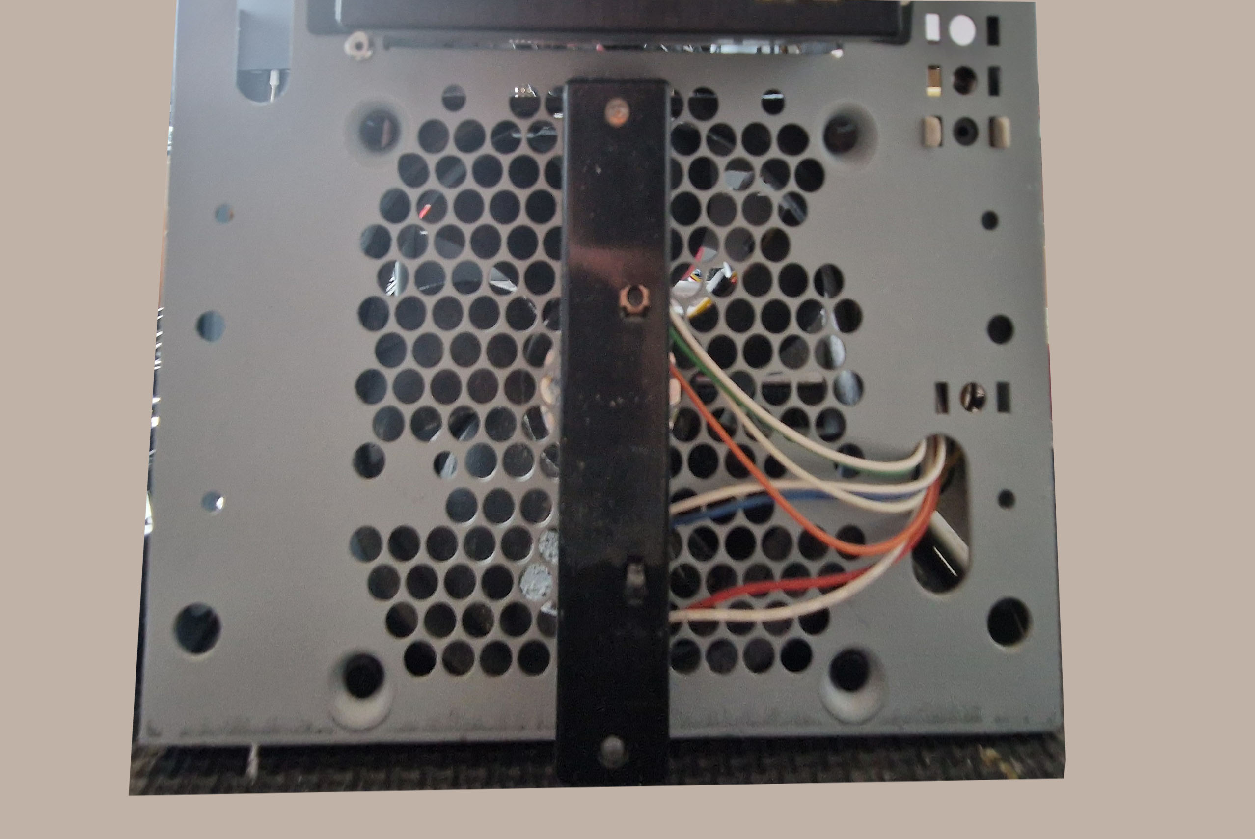
There are a number of fans in the system: in the power supply, in the CPU cooler, in the graphics card cooler, one at the front of the case and one at the back of the case.  I could reach all these to de-dust them, except for the one at the front of the case, which is sandwiched between the front metalwork and the hard drive cage and is held in place by four plastic pegs.  The first problem was how to remove the front cover panel of the computer.

Step 1 – Remove side panels

It’s a tower computer in a large case.  The side panels are held on by thumbscrews on the back of the case.  You unscrew these, slide the panel backwards about 1 cm and then just lift it off.  I took both sides off.

Step 2 – Remove front cover
Inside of front cover moulding

The front of the case has a plastic cover over the metal case behind.  It is not obvious how it is held on, but it has plastic pegs along each side  edge. You can see the ends of these when the side panels are off.  You can carefully push them out from the inside of the case or insert a broad-bladed screwdriver between the metal case and plastic panel and gently  lever them off, taking care not to damage the paint.  On my machine, there is nothing fixed to the front panel, so you can just lift it away.  Clean out all the dust!

Step 3 –  Remove the fan fixing pegs
Front of case-showing four fan fixing pegs

Now you can see that the front panel fan is held in by four hollow plastic pegs with a centre pin that spreads the legs which are  on the inner end, thus holding the peg in place.

Fan Fixing Peg

To remove them, use a thin screwdriver to push the centre pin back into the hollow peg.  The head of the pin then protrudes on the front end and you can easily pull the whole peg out. Be sure to save them.

Step 4 – Remove the hard drive cage
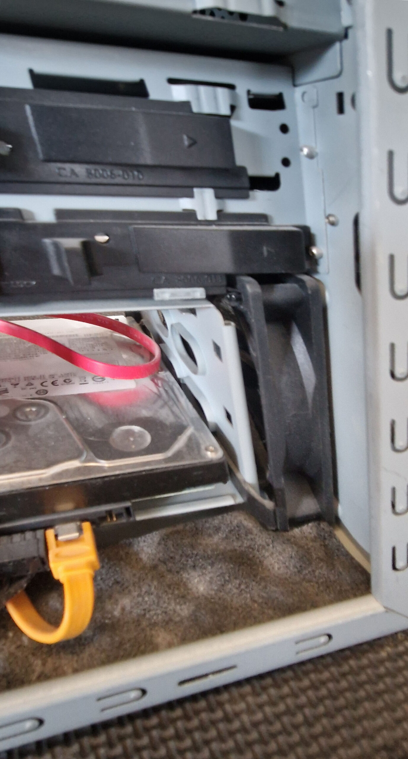
Fan sandwiched between case and hard drive cage

The fan is now loose, but no way will it come out because it is sandwiched between the front panel and the hard drive cage.  You’ll have to release the cage.  Firstly, carefully remove the plugs from the hard drive – take a photo to be sure of getting them back correctly.  Then lift out the hard drive and carefully dust it.  This is the personality of the computer, so treat it very carefully and avoid any bumps.


Screws securing hard drive cage circled in red

But the cage is firmly secured. after much investigation, I discovered that it was held in place by two screws into the side panel and two screws into the base of the case.  When these were undone, it came free, but I couldn’t remove it entirely because someone had quite unnecessarily threaded a cable through one of the unused holes in the case.

Hard Drive case removed

There was enough slack for me to move it out of the way without unplugging it. I could now lift the fan out.  However, the power connector is plugged into the motherboard, so I had to unplug this, taking care to press the holding catch on the plug so it would come out without any force.

Front case fan removed

Putting the new fan in was just a reverse of this process: Of course, you might not be sure which way round it goes: I just made sure the power leads were in the same place as the original. For information, the fan is a standard 120 x120 x 25 mm fan with a 12 V motor and a 3-pin power connector. I bought what I hope is a good-quality fan that will run quietly for a long time.

DID THIS WORK?

To my relief, the computer started up correctly, but the awful rattling and squealing started after a while and I realised that the real problem was the fan in the graphics card.

New Graphics Card

It’s not easy to decide what to do when it is an aging computer, but I have lot of information on it and it would take a long time to set up a new one.  I’ve decided  to buy a new graphics card.  I do a fair bit of video editing but I don’t play computer games.

After brief research, I decided on a SWFT210 Radeon RX 7600 card.  This is suitable for my motherboard and is much faster than the old card.  It has 8 GB of memory, compared with 1 GB for the old card, and has a 2 GHz clock compared with 800 MHz for the old card and it was in stock at EBUYER for next day delivery at a very reasonable price.

For me, the only down-side is that it has 3 Display Port sockets and one HDMI socket. I use two displays, one with DP, but the other needs a VDI input. After a short search, I realised that VDI connectors are a thing of the past, but you can get a DP to VDI adapter for very little, so that’s what I’ve decided to do.

Power Supply

The graphics card is the sensory input/output of a computer, so changing it is a major thing.  The specification says you need at least a 550 W power supply for the computer system when using this card, although it is rated at a 200 W power consumption itself (which is not insignificant).

I had already replaced the power supply in the computer with a Corsair 850X unit (which is 850 W as the name implies), so this was fine.  However, I hadn’t thought about the power connector.

After removing the old graphics card and carefully fitting the new one, I was concerned to see that the new card needed an 8-pole power connector, whilst the old card had a 6-pole connector!  After a cold shudder ran through me, I noticed that on the cable with the 6-pole connector there was another wire with a two-pole connector and the polarisation of the connectors was such that they fitted alongside each other into the 8-pole socket!  Clever! the cable could be used for this card, but wasn’t something I’d considered when choosing. Apparently some of the more powerful cards need even more connections, so it is something to take into account: the publicity information blathers on about various features without mentioning this rather more fundamental requirement!

Drivers

The next thing is to fire up the computer – I was relieved when it gave the startup bleep and even more so when the login screen appeared. The boot-up resolution is apparently VGA and you have to download the correct drivers.  To be fair, AMD have automated this and one you log into the right part of their website, it will download and install the correct driver.  It took a fair while, but worked without issues.

Silence in Court!

I’m delighted to say that the system is now running with virtually no fan noise at all, although the heatwave has passed so it’s not such a demanding environment right now.

It’s been a worrisome few days, but so far, so good. I must now think about my backup system.  That disk drive has done 50,000 hours and they don’t last for ever …

Capacitor Labelling

I find the labelling of capacitors quite confusing.

The ability of a capacitor to hold an electric charge (its Capacitance) is measured in Farads.  One Farad is the ability to hold a charge of 1 Coulomb with a potential difference across the capacitor of 1 volt.  [One Coulomb of charge is the amount of electricity that flows when a current of One Ampere passes for one second.}

For practical purposes, a Farad is a huge amount of capacitance.  In most circuits, values range from maybe 200 μF to 1 pF.  It is not always clear how the value of the capacitor has been labelled: because they can be small devices, some form of code is used and you have to be able to understand the code to be sure you have the right component, whereas with resistors it is easy to measure the value if you’re not sure.

Ceramic capacitor labelling

These are labelled in picofarads (pF).  If there are one or two digits, that is their capacitance, eg a label ‘5’ means 5pF.

If there are three digits, the first two are the value and the third is the multiplier. For example a value of 103 means 10 pF times 10³, i.e. 10,000 pF.  This same value would probably be shown in circuit diagrams as 10 nF or 0.01 µF.

The following table helps you to convert between the thousands used in Engineering notation:

Farad, F microFarad,
µ (10-6 F)
nanoFarad,
nF (10-9 F)
picoFarad,
pF (10-12 F)
1 1,000,000
1 1,000 1,000,000
0.1 100 100,000
0.01 10 10,000
0.001 1 1,000
0.1 100
0.01 10
0.001 1


Worn-out Keyboard Lettering

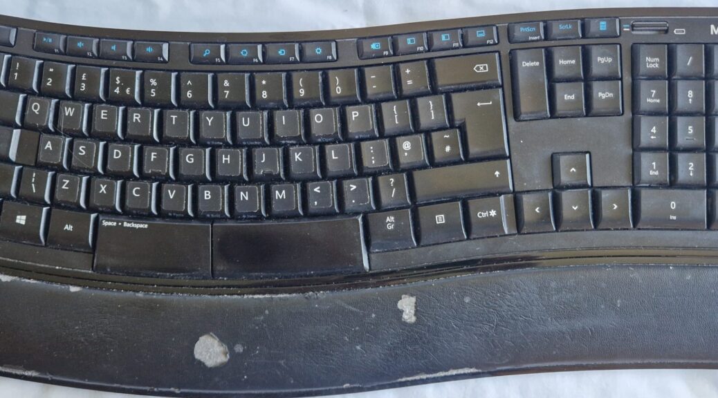
I use a Microsoft ‘Sculpt Comfort’ keyboard bought in 2012. I like using it and it works fine, but the lettering has worn off all the main keys.  Since I’m a touch typist, this wasn’t a problem until I started learning Morse, when I was overwhelmed by extra mental effort of listening to the signal whilst hitting the right keys.  Sadly, it seems that no-one is making a similar replacement keyboard.  I’d tried putting paper stickers on the keys, but these couldn’t withstand the rather fierce pounding I was giving the poor old thing.

Keytop labels
Keytop labels

Then I found proper plastic keytop stickers on-line at Amazon.  These are amazing.  I vacuumed then cleaned the key tops carefully first with a cloth damped with detergent and then with a tissue dampened with Methylated Spirit (alcohol) to ensure that grease and gunge was removed.  Then all I had to do was remove the stickers one at a time from the backing sheet, putting them carefully into place using tweezers and then pressing them down firmly.  I’m really impressed by the result – unless you look carefully, you wouldn’t really notice what has been done, and now I can’t blame the keyboard when I hit the wrong key!

The keyboard still shows up dust and I’m aware that the wrist-rest is tatty. I’ll need to find a way of re-covering it, but it’s not a priority right now.

Connecting a Reolink E1 Outdoor PoE camera directly to a PC

As the name implies, this camera is a network device, not just a simple video camera: it doesn’t have a HDMI or other video port, so you can’t just view it on a computer or TV display.

This means that it sits at a particular IP address and sends a video stream in an internet format which has to be decoded in a computer before it can be displayed.  The video stream can be decoded either with the dedicated Reolink App or in an ordinary web browser.  My testing shows that the App is better, providing less delay and more functionality.

I want to use a laptop for hosting the App.  Normally I could just connect the camera to my LAN, login to the App via my WiFi connection and view the camera.  However, I want to use this in the church tower where I do not want to connect to the church’s WiFi network – I want to plug an Ethernet cable directly between the camera and the laptop (running Windows 10).

The first consideration is that the camera requires power. I have chosen a Power over Ethernet (PoE) camera, which takes power via the Ethernet cable, but a PC doesn’t supply power from its Ethernet connection, so I need an Ethernet Power Injector.  I bought a TP-Link PoE+ model POE160S for this, as it automatically supplies the correct current.  It has two gigabit Ethernet ports, one for data in/out, which I connected to the PC, and one for data+power which I connected to the camera. The PoE Injector also has a socket for mains in – there’s no need for a separate power adaptor.

I have already given the Camera a static IP address of 192.168.1.252
This means that I don’t need to have a DHCP controller (router) to assign a network address – I will be using its known, static address.

To avoid conflicts potentially caused by the LAN router, firstly I need to turn off the laptop’s WiFi network.  I just click on the WiFi icon in the taskbar and select ‘disconnect’.

Now I plug in the Ethernet Cable and go to the Network and Sharing Centre on the laptop. Here I see that there is a connection called ‘Ethernet’ and I click on its name to open its Status dialog, showing ‘No network access’.  I click on the Propeties button and select IPv4 and again select Properties.  This enables me to set the properties of the IPv4 connector (adapter) on the  laptop.

I click ‘Use the following IP address’ and enter 192.168.1.240
This is essentially the IP address of the laptop.

The important thing about this is that both the laptop and the camera are connected to the same node (the 1 in the third group above)
I also set the subnet mask to 255.255.255.0 and leave the default gateway blank.

I set the DNS server to 8.8.8.8 and the alternative to 8.8.4.4

These are essentially null values as there is no DNS server or internet gateway – the laptop /camera network is isolated from other devices.

I can now use the Reolink app which should detect the camera, from where I can instal it.

Reverting

The downside of this adjustment is that you have disconnected your LAN and the Internet from the laptop.  In order to restore it, you need to reconnect the WiFi. You can do this by going to the WiFi icon in the taskbar and just reconnecting WiFi.

However, I found that after reconnecting the WiFi I was able to access all the LAN resources and this included viewing my other Reolink camera which is connected to the LAN via my Network switch.

It’s taken a bit of effort to get to this point, so I hope I can help others by sharing it.

Installing a Reolink E1 Outdoor PoE IP Camera

The need for a PoE camera

My Reolink PoE camera, described in an earlier post, has been working well for nearly 4 years: now I have a requirement for another camera with remote PTZ (Pan, Tilt, Zoom) control, so I have bought another Reolink as captioned above.

The bells, the bells

I look after the tower bells at St Andrew’s Church, Cobham.  A peal of bells is a heavy mechanical installation that requires constant inspection, maintenance and repair.  The heaviest bell at St Andrew’s weighs half a ton and the lightest weighs 3 cwt (150 kg): the eight bells weigh a total of just over 2 tons (tonnes). The bells swing through 360 degrees (but don’t go right round, of course) and this puts a lot of force on the bell, its suspension, the supporting frame and on the tower.

Access to this tower is difficult.  There is a pull-out ladder about 5.5m (18 ft) high, then a trapdoor through the ceiling into a chamber 2 m (6.5 ft) high which has a vertical steel ladder through another trapdoor into the clock-chamber.  This is where in the old days the clock winder had to climb at least once a week to wind the clock, which had three heavy weights, one for the going train, one for the quarter chimes and one for the hour chime. Now the weights are wound electrically.

To reach the bells, there is another clamber up a 2 m (6.5 ft) vertical ladder to reach the bottom of the bell frame.  The eight bells are stacked on two levels, and to reach the top level (which has bells 2, 3 and 7), it is necessary to scramble up another 2 metres (6.5 ft) through the pit of bell 6.  Overall it is a 40-foot climb making it impossible to take visitors to see the bells and it’s a messy job to undertake inspections.

This an obvious case for a PTZ camera with PoE (Power over Ethernet) so that only one cable needs to be fed up the tower and it can all be controlled at ground level.  At present I haven’t worked out the optimum positioning of the camera, but hopefully it should be possible to get a good view of most of the bells.

After some research, I decided that the Reolink E1 Outdoor camera would suit me.  The bell-chamber is sheltered from rain, but otherwise essentially in a harsh outdoor environment – cold, sometimes hot, damp, windy and dusty.

Connecting the camera to a network

The first step  in testing the Reolink E1 Outdoor  was to get it connected to the existing Reolink app on my main machine (which displays the cameras on the house). So firstly, I plugged an ethernet cable between the camera and my PoE network switch.  I then started the Reolink App (although you can view in an ordinary web-browser – more later)  and clicked ‘Add Device ‘ in the Device sidebar. The Add Device dialogue opens and scans the network.  The new camera appeared and I clicked the + button.

The dialog  asks you to give the admin password and you may want to change this to one of your choice.  Here, you need to be careful because the app remembers this password and also stores it in the camera.  The App automatically uses it next time you start the app (so you don’t need to reconnect to the camera each time you start the app).

Device Already Connected Error Message

However, if you have already logged in on a different machine and used the default password, changing it on the new machine will mean a world of pain on the first machine.  This is because that machine is still using the old password to login, but the camera has stored the new password internally.  So it will refuse to connect.

Worse still, because you don’t have the right password you can’t delete the camera in order to reinstall it with the correct password, nor can you try to reconnect it with the new password because you get the message that the ‘Device is already connected’ .

Ultimately, I found that on the computer that did still connect, by going to the Camera Settings dialogue and then System>User Management, I could put in a new username and password with admin status and then I could reconnect on the other computer using these new login details. Once I did login on that computer, I could change the admin password on that machine too. This enabled me to delete one of the connections.

I  would advise against selecting ‘Illegal Login Lockout’ in the User dialogue at this setup stage, as you’re probably going to be making quite a few unsuccessful logins!

However, it will be a good idea to go to Network in the Camera Settings dialogue  and in the Network information window, choose setup.  In connection type, select ‘Static’.  This will mean that the IP address will remain fixed, rather than possibly changing at the whim of your DNS/DHCP controller, which might mean that you would need to reconnect it. The camera’s IP address should be on the same node as your WiFi and router, so if your router is at 192.168.1.254, you might choose something like 192.168.1.250.  (The octet 250 must not be in use by any other device on your network.) At this stage, make a note of the camera’s IP address as you’ll need it when connecting direct to your laptop later.

So now it is working when connected to a network switch.

The next step is connecting directly to a PC.

Pipe Threads and Quooker Filters

I have a Quooker ‘Boiling Water Tap’ that was installed in 2020.  Since the water in Epsom is basically ‘dilute cement’, coming from a borehole in the chalk  (water hardness 24 ° dH), I had a limescale filter (water softener) fitted into its supply line, but this needed changing every 6 months and at £80 a pop, this was an expensive business.

Clearly I wasn’t the only one who thought so, because in 2023 they said they were discontinuing that filter and introducing one with a higher capacity – and a higher price, of course.

One of my New Year jobs was to fit this new filter. Unfortunately, the Quooker instructions were far from clear – mainly consisting of diagrams that had to be read with some rather terse instructions.  I know from my own experience how hard it is to write clear instructions: the lack of labelling on the diagrams gave me the impression that this was to make them ‘language neutral’ – they could use the same diagrams for instructions in various languages.  Moreover, I realised that the instructions that came with the new filter did not include how to take out the old filter.  Naturally, I presumed that I just needed to take out the old one and connect the new one in  its place.

WRONG!  The connectors wouldn’t marry up to the existing pipe ends. So I explored the Quooker website and found a download of how to substitute the new filter in place of the old one.  But this wasn’t straightforward, because there are several different models of boiler and the first task was to identify it from the model number, of which there are quite a lot. Mine was a model PRO3 E and a particular feature of this is a pressure relief valve in the water supply line to the boiler. The original ‘Scale Control Plus’ filter was mounted between the incoming water supply and the inlet of the pressure relief valve, whereas the new Scale Control R had to be fitted between the outlet from the pressure relief valve and the inlet to the boiler. Perhaps we shouldn’t be surprised that this is not mentioned anywhere: you have to deduce it from the diagrams.  But it makes sense because then the various adaptors that they supply do enable you connect the new filter in place.

But now I had a problem – there was a stonking great gap of almost a metre between the water supply inlet and the pressure relief valve.  The instructions casually show a short piece of copper pipe (not supplied) to bridge this gap.  Except that because the old filter had around a metre of plastic tubing between these two points, it would be a major plumbing job to get some piping, cut it to size, solder two 90-degree elbows and fit it all in place with connectors, olives and what-have-you all in an awkward space in the cupboard underneath the sink.

Then I had a brainwave –  I could do this with a flexible pipe.  After all, the other connectors to the filter and boiler all had flexible tubing.

When is ¾ inch actually ½ inch?

Now we enter another maze.  I measured the outside diameter of the threaded (male) connectors of the two ends that I needed to join.

I measured these as having around 18 mm external diameter screw thread, but when I looked on the Screwfix website, the screw thread connectors all seemed to be imperial.  The nearest was fitting was for a ¾-inch external diameter and I ascertained that I would need a pipe about 80 cm long.  Looking through the Screwfix and similar websites, I couldn’t find long flexible pipes: there were some that said ¾-inch to 22 mm, which puzzled me until I realised that the 22 mm was the size of a compression fitting onto 22 mm tubing.

Then I saw that a washing machine hose was plenty long enough and had ¾-inch connectors.  Not ideal for a permanent water connection, but I could find a proper reinforced flexible pipe on-line for later delivery.

Disaster! ¾-inch connectors are actually 1 inch in diameter! They were far too big. How come?  It turns out that  ½-inch connectors are actually ¾-inch diameter! It’s because historically, pipe sizes relate to the internal bore of the pipe, not its outside diameter, and you have to allow for the thickness of the pipe wall.

Internationally Imperial

And even more surprising, despite all the hype about returning to imperial units in the UK, it seems that for pipe connectors we have remained imperial, even to the point that the sizes are internationally standardised as BSP (British Standard Pipe) sizes – except of course in USA where they have their own system.

Confusingly, the external diameter of pipe threads are actually ¼-inch larger than their nominal size!

So a half-inch flexible pipe is required to connect to  the ¾-inch outside diameter of the actual connectors.  Luckily I was able to buy these easily on line. Wey-hey!

Parallel vs Tapered threads

Now we come to another little wrinkle regarding pipe threads.  One end of the connector fitted without problems onto the stop valve for the water supply, but I had difficulty getting the other end to pull up tight onto the inlet to the pressure relief valve.  Eventually, I realised that the inlet at that end had a tapered thread! Yes, BSP threads come in BSPP parallel threaded  and BSPT tapered versions.  The idea of the tapered version is that as you tighten the connector, the tapered thread binds to the connector’s thread and ensures it is water-tight.  However, I had to put some graphite lubricant onto the thread in order to get it to pull up tight to the washer in the connector- even then using two large spanners.

Anyway, thank goodness it all works now. But it was far more difficult than it would have been with clear instructions – including something as simple as details of the pipe thread required – and I literally have the scars to prove it!

Decorative Flicker Lights

My house has a period brick fireplace that had a ‘living flame’ gas fire in it, but I had the chimney taken down when having an extension built.  But a dark fireplace is uninviting, so I bought a ‘Silk Flamelight’ which looks fine, and it has a ‘tape’ of red LEDs in the base to give the effect of glowing embers.  I like it, but it would be nice if the glow of the embers could wax and wane as in a real fire.

I did try out some ‘flame effect’ LEDS, but I don’t like them because the flame is clearly periodic and ultimately quite annoying.  It seems that these are powered via what are essentially counter chips with feedback connected to give some pseudo-randomness.

But I came across some red ‘candle flame effect’ LEDS. These have some sort of microscopic randomiser chip within them.  They do flicker nicely,  but they are not bright enough.

The wiring diagram for the booster circuit
Figure 1 Booster Circuit Wiring

It occurred to me that I could use the varying voltage on the anode of the LED to drive a simple transistor amplifier, as shown in the diagram.  The resistor R1 in series with the anode of the flicker LED  will cause the voltage on the anode to vary according to the current that it is drawing. If we assume this is to be 10 mA when fully on, the voltage drop across a 200 Ohm resistor is  is nominally 2 v, giving an anode voltage of 3 v, which is the nominal forward voltage of the flicker LED.  When it is fully off, the voltage will rise to the supply voltage of 5 v.

This range of 3 v to 5 v needs to turn the transistor TR1 off and on.  By placing the bright LEDS on the emitter of TR1, and assuming they have a forward voltage of 2 v, then TR1 will conduct whenever the voltage on its base exceeds about 2.6 v, because a transistor has a 0.6 base-emitter voltage drop.

This means that the bright LEDs will always be on a little, and will be at their brightest when the flicker LED is off.

Effect of changing resistor values

Resistor R1 affects the range of voltage at the base of TR1 – experimentation show that a value of 100 ohm meant that TR1 was always fully on, and a value of 350 ohm increased the amount of flicker from fully on to fully off.  However, since embers are always glowing to some degree, a value of 200 ohm was thought to be optimum.

The value of R3 affects the current draw of the bright LEDs, so needs to be chosen taking into account their forward voltage.  Assuming this is 2 v, then a 100 ohm resistor gives 15 mA per diode in the arrangement shown, or 30 mA if only one diode.

LED ‘Tapes’

To simulate the glow of embers in a grate, I need a row of LEDs, and it occurred to me that an RGB strip of LEDs would allow me to control their colour which would be nice.  A search showed that LED ‘tapes’ (a long line of surface-mount LEDS fixed to a backing tape) have the resistors in series with each group of diodes.  The LED tapes are designed to use a common positive rail, usually 12 or 24 volt, so they need to be in the collector circuit of the output transistor. A separate circuit is needed for each colour.  This will require some reworking to accommodate these factors.

blocking capacitor
Figure 2 Using blocking capacitor

The problem is to get the right biasing of the output transistor. As we have noted, the voltage at the junction of R1 and the Flicker Diode varies between say 3 v when fully on up to the supply voltage (now 12 v) when fully off (it’s not possible to measure accurately with my digital multimeter as this only samples about twice a second.)  One solution is to use a DC  blocking capacitor in the transistor base circuit, as in Figure 2.  The 20 k resistor allows the voltage on the base to build slowly (the time constant is 20 k x 10 µ = 0.2 sec), so the voltage on the base will follow that on the flicker diode but without the DC bias.

Flickering Embers

This actually worked very well in terms of conveying a strong flicker to the output, but I want to put the tape of LEDS into the bottom of the hearth to look like flickering embers, and these don’t switch quickly on and off, but gently vary with the air flow through the grate.

The glow of embers varies between bright red and bright yellow. Yellow is produced by mixing red and green, and after some testing I decided that the red needed to be at full intensity all the time, and only the green needed to flicker.  More than that, with green at full intensity, this drowned out the red, and we had green embers – not at all natural!

Flicker Circuit 3 Using biasing resistors

So, ultimately, I ended up with circuit 3 .  This uses a fairly high value of 6.4k for R1 in the anode of the flicker diode: it still flickers as required, but is fairly dimly lit. This doesn’t matter since it is only being used to generate a flickering voltage to the transistor.  R2 and R3 act as a potential divider and apply a voltage varying between 1.2 and 4.8 volts on the base of the transistor, so it is always conducting.  This is fine – it means the embers are always slightly orange.  In fact, they were slightly too orange, and it was necessary to put a 100 Ω resistor in series with the output to the green LED channel.

This works fine – if I have any disappointment, it is that I don’t seem to be able to get a really bright yellow: increasing the green channel seems to go rather suddenly from orange to green, but maybe I didn’t experiment enough. For information, the values of the resistors are not critical.  Reducing the value of R3 increases the amount of flicker but reduces the overall brightness, because the transistor has a lower amount of base bias.  Increasing the value of R2 reduces the brightness because it also reduces the amount of base bias.

Elegance

Although this works acceptably well for my fireplace glow, and is extremely economical on components, I’m not sure how engaging it would be for garden ‘party’ lights.

It seems to me that we could use the output of the flicker diode to modulate the output of a pulse width generator. It appears that this can be done with a 555 ‘timer’ chip, but this is a whole new ball game for me.  This chip, which is very inexpensive, is essentially a multivibrator which can be controlled by external resistors and capacitors to produce monostable and astable (usually square wave) output.  The 555 is very cheap and has enough switching capacity for a short LED strip.  For larger strips you would need to buffer the output through a power MOSFET.

I’m thinking I will try this out and let you know if it works.